Fire severity has recently increased in Russia. The growing number of storeys in capital construction projects is one of the reasons, another one is change in the functional purpose of many buildings. Unfortunately, fire safety requirements remain outdated when compared to the pace of modern construction. People have less and less chances for safe evacuation from such buildings. As for people with disabilities, they have even fewer opportunities for getting out of fire and smoke.
This website is devoted to a unique invention, i.e. emergency evacuation device for high-rise buildings (metal ladder).
Mikhail Kobzev and Leonid Kaleta obtained two patents for the invention “Emergency evacuation device for high-rise buildings” in April 2018 and in December 2020.
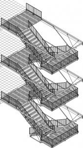
The project of the ladder (the invention) offers a new approach to rescuing people in case of fire in multi-storey and high-rise buildings, buildings which are under reconstruction and remodeling, buildings with the increasing number of people with disabilities inside, as well as in entertainment and sports complexes, at stadiums and in many other buildings.
Evolution of the ladder project from invention No. 2651656 (RU) patented in 2018 to invention No. 2737940 (RU) patented in 2020.
1. Original version – The level of the ladder landing platform is set by the length of the guy ropes. Horizontal direction of the ladder landing platform is set by the upper pantograph, which consists of four beams.
Modern version – The level and horizontal direction of the ladder landing platform is set by the pantograph, which is transformed into two power trusses.
2. Original version – Direction of steps of the lower span is set by the lower pantograph, which consists of four beams, and the length of the guy ropes.
Modern version – Direction of the steps of the lower span is set by two folding structural elements. Each folding element consists of an upper and lower part. These parts are connected by the common axis.
3. Original version – The center of rotation is set by a circumferential strip made of plate material and rollers resting on the strip. The support strip is fixed to the building. The rollers are mounted on the ladder frame.
Modern version – The center of rotation is set by a group of plates with a cutout centre. The rollers rest on this circumference. Support plates are mounted on the ladder frame. A group of support rollers are mounted on the building.
4. Original version –Rotation is set by the load, which is released by the locking pin. A limit stop and buffers ensure the end of rotation. The weight of the load is transferred to the frame with the rope and the circumferential strip made of plate material.
Modern version – The triggering load and the breaking load ensure rotation and stop of the ladder. The triggering load is released by the first locking pin and is divided into two parts after acceleration. It changes direction of circumferential force and ensures smooth stop of the mechanism in the position set by the second locking pin. The heavy part of the triggering load is fixed in the second upper dead center of the pendulum of loads by the third locking pin. The weight of the loads is transferred to the frame with the help of a group of ropes and rope connectors that move along the guides. The ropes are fixed with rope eyes at two points of the frame.
5. Original version – The ladder railing is raised with pneumatic air cylinders. Railing is fixed with latches in the vertical position.
Modern version – The ladder railing as counterweights and is raised automatically after removal of locking pins. The railing is fixed in the vertical position with plain bars come out under their own weight.
6. Original version – The handrails of the ladder are flexible and made of ropes.
Modern version – The handrails of the ladder are rigid and made of plate parts with stiffeners.
7. Original version – The supporting frame of the ladder has all welded structure.
Modern version – The supporting frame of the ladder consists of four parts that are screwed together after transportation.
Advantages of the modern version of the transformable ladder:
1. Replacing the ropes with a truss significantly increases resistance.
2. Replacing the lower pantographs with a folding structure significantly increases resistance by halving a console. Elimination of ropes increases resistance as well.
3. A curved strip made of plate material is not technologically infeasible. Replacing it with plates with round openings significantly reduces the price of the device.
4. Introduction of the system of triggering and breaking loads prevents strong blows, which require expensive buffers for compensation. It reduces the price of the device and makes building operation safe.
5. Introduction of the railing with counterweights significantly reduces compressed air consumption, which is required to open the ladder. As a result, the maintenance period for the device is noticeably extended.
6. Introduction of rigid handrails significantly increases railing resistance. It makes evacuation safer.
7. Division of the supporting frame into four modules ensures transportability of the disassembled device at any distance using a standard trailer.